What Is S11?
S11 is the input reflection coefficient of a network, normally measured at a 50 Ω RF port. In simple terms, it answers one question: how much of the RF signal sent into the antenna comes back toward the source?
When an antenna is perfectly matched to a 50 Ω system, there is no reflection at the input. Real antennas are never perfectly matched across every frequency, so some energy is reflected. A Vector Network Analyzer (VNA) measures this behaviour and displays S11 as a function of frequency.
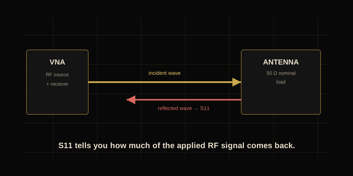
S11 is normally shown in negative dB. More negative means less reflection. Therefore −20 dB is better matched than −10 dB.
From Reflection Coefficient to S11
The underlying quantity is the complex reflection coefficient, usually written as Γ (Gamma). It is the ratio of reflected voltage wave to incident voltage wave.
Because power is proportional to voltage squared (for the same reference impedance), the reflected power fraction is:
That second equation is the key to understanding what an S11 number actually means in a real RF system.
How Much Power Is Reflected?
Here are useful reference points. The numbers describe mismatch reflection only; they do not include cable loss, dielectric loss, conductor loss or radiation efficiency.
| S11 | Reflected power | Power not reflected | Reflection coefficient |Γ| |
|---|---|---|---|
| −3 dB | 50.1% | 49.9% | 0.708 |
| −6 dB | 25.1% | 74.9% | 0.501 |
| −10 dB | 10.0% | 90.0% | 0.316 |
| −15 dB | 3.16% | 96.84% | 0.178 |
| −20 dB | 1.00% | 99.00% | 0.100 |
| −30 dB | 0.10% | 99.90% | 0.0316 |
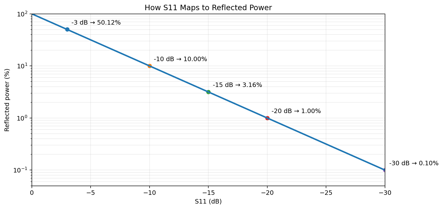
−10 dB does not mean 10 dB of loss. It means the reflected power is 10% of the incident power. The remaining 90% is not reflected — although that does not automatically mean all of it is radiated.
S11, Return Loss and VSWR
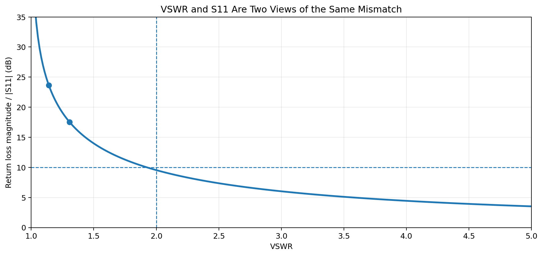
You will often see S11, return loss and VSWR listed next to each other. They describe the same impedance-mismatch behaviour in different forms.
| Parameter | What it expresses | Better value |
|---|---|---|
| S11 | Reflection coefficient in dB | More negative |
| Return loss | Positive dB representation of mismatch | Higher |
| VSWR | Standing-wave ratio | Closer to 1:1 |
How to Read an S11 Plot
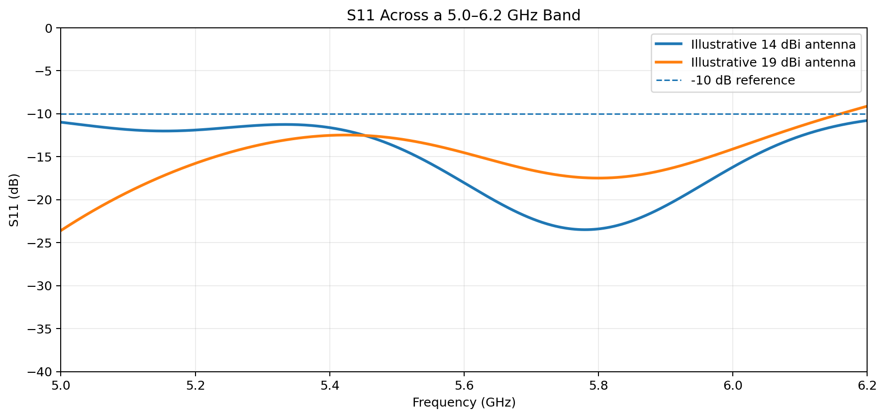
An S11 plot normally has frequency on the horizontal axis and S11 in dB on the vertical axis. A deep dip means the antenna is better matched at that frequency.
- Find your operating frequency. For a 5.8 GHz FPV system, inspect the S11 value around 5.8 GHz — not just the deepest point anywhere on the graph.
- Look at the intended bandwidth. An antenna may have an excellent −30 dB dip at one frequency but perform poorly elsewhere.
- Use −10 dB as a practical reference. It is a common threshold for defining an impedance-matched operating region, but the right specification depends on the application.
- Do not confuse matching with efficiency. An antenna can have excellent S11 and still lose energy internally. S11 alone cannot tell you gain, radiation efficiency or polarization quality.
What Does S11 Look Like on a Real 5.8 GHz Antenna?
Kreita's EGLE-16C-1R is specified for 5.0–6.2 GHz and has a measured S11 of −23.45 dB at 5.8 GHz, corresponding to about 0.45% reflected power at that frequency. Its listed VSWR at 5.8 GHz is 1.141.
The larger EGLE-64C-R is also specified for 5.0–6.2 GHz. Its measured S11 at 5.8 GHz is −17.58 dB, corresponding to about 1.75% reflected power, with a listed VSWR of 1.306.
These examples show an important point: the larger, higher-gain antenna does not need to have the numerically lower S11 at the centre frequency. S11 is an input-matching parameter, not a direct measure of antenna gain.
For the EGLE series, the published S11 values are measured RF data. Always use the current product page/datasheet for the exact unit and measurement conditions rather than assuming an illustrative graph represents the antenna.
Good S11 Does Not Mean Good Antenna
This is one of the most important RF measurement concepts. A very low S11 only tells you that little power is being reflected from the antenna input. It does not prove that the antenna radiates that power efficiently in the direction you need.
- Gain tells you how strongly the antenna radiates in a direction.
- Radiation efficiency tells you how much accepted power is converted into radiation rather than lost as heat or dielectric/conductor loss.
- Radiation pattern tells you where the energy goes.
- Polarization tells you how the electric field is oriented or rotates.
- Cross-polarization rejection tells you how strongly the antenna suppresses the opposite polarization.
A useful way to think about the chain is:
How Is S11 Measured?
A VNA measures S11 by generating a known RF signal at the test port and measuring the signal returning from the device under test. Before measuring an antenna, the measurement path is normally calibrated so that the reference plane is moved as close as practical to the antenna connector.
For a coax-fed antenna, connector quality, cable movement, calibration quality and the physical test environment can all affect the measured result. This is why a published S11 curve should be interpreted together with its measurement conditions.
If you are comparing two antennas, measure them using the same VNA, calibration method, reference plane and frequency sweep. Otherwise, differences in the measurement setup can look like antenna differences.
- S11 is input reflection measured at an RF port.
- More negative S11 is better matched.
- −10 dB = 10% reflected power.
- −20 dB = 1% reflected power.
- S11, return loss and VSWR are different representations of the same mismatch behaviour.
- Good S11 does not prove high gain, efficiency or good radiation pattern.
- For antenna selection, evaluate S11 together with gain, bandwidth, polarization, beamwidth and radiation-pattern data.